Contents:
- Planning Your Underfloor Heating System
- Installation
- Filling The System
- Controlling the System
- Commissioning the System
1. Planning
We can supply a complete CAD design for systems if required. However, for your assistance, we have listed below some of the main considerations to take into account when planning your underfloor heating system.
- Manifold Location – a primary consideration at the planning stage of your underfloor heating solution should be the ideal location for the manifold. All flow and return underfloor heating pipes will travel to and from the manifold and therefore it should be ideally located centrally between all rooms to be heated. The pump/temperature control unit fits directly to our manifolds and the wiring centre is installed alongside the
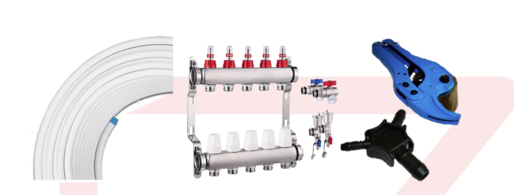
manifold. - Type of Pipe – a multilayer pipe with an aluminium core (either Pex-Al-Pex or Pert-Al-Pert) is ideal for modern underfloor heating systems as it ensures maximum heat transfer, balanced with the assurance of a very strong and robust pipe. WRAS approved pipe has the added advantage that it offers an assurance that it has been through a rigorous testing procedure to ensure it is suitable for use with drinking water in the United Kingdom. Our 16mm Pex-Al-Pex underfloor heating pipe is UK WRAS approved and certified. Therefore, in addition to underfloor heating, it can be used for plumbing for which we also stock a full range of fittings (any excess pipe from underfloor heating can be used for plumbing). Pex-Al-Pex and Pert-Al-Pert pipes have the added advantage of having a bend memory and will not try to revert back to their coil shape when being installed and do not need bend formers like some older type pipes.
- Pipe Spacing – as a guide, for properties insulated to current building standards and with a supply water temperature from the boiler of at least 50 degrees Centigrade, pipe spacing will normally be 200mm pipe centres. However, factors such as high glazing content, poor insulation values, and lower water supply temperatures (such as from some Heat Pumps), can affect the required pipe spacing and mean a closer spacing is required.
- Pipe Loop Length – we recommend maximum pipe loop length of 100 linear metres for 16mm pipe and 80 linear metres for 12mm pipe. These measurements include the run to & from the manifold.
- Quantity of Pipe – 100 metres of 16mm pipe will cover a room of 20.0m² at 200mm pipe spacing, assuming the manifold is within that room. For larger rooms, multiple loops of pipe are used and connected to multiple ports of the manifold. Our pipe is marked every metre and therefore very easy to monitor your loop length as you install.
- Pipe Installation – Pipe is installed to within 100mm of the room perimeter walls. For in-screed underfloor heating systems, pipe is fixed to insulation with pipe clips at a rate of approximately 1 clip every 50 to 100cm. We also have to fix options such as grip rails (1.0metre long interlocking rails that fix to the insulation and the pipe clips into the rail) for ease of installation if preferred. You would not normally install below kitchen units. We can also offer a range of overlay options where pipe can sit in pre-routed boards or specially designed panels.
2. Installation
If we have supplied you with a pipe layout design, you can follow this during your installation process, in conjunction with the points detailed below where appropriate.
- Manifold – your manifold is supplied pre-installed to a fixing bracket. Screw the bracket to the wall leaving the bottom of the manifold approximately 400mm above floor level. Ensure you allow at least 200mm to the left side of the manifold to allow for the connection of the pump/temperature control unit.
- Pump & Temperature Control Unit – The pump unit is supplied with all fixings to screw directly onto the left side of the manifold. The unit is designed to fit to the manifold and will line up directly to the manifold fittings with no extra seals or fittings required.
- Pipe – Pipe is easiest installed by 2 people – one person rolling out the coil and one person following behind pushing the clips in. Alternatively, installation can be eased by using one of our Pipe Decoilers to hold the pipe and our clip (tacker) gun to insert the clips. If manually rolling out the pipe coils it is best practice to hold the coil between your legs and roll it out in front of you as you go, whilst your colleague follows behind fixing the pipe to the insulation with clips.
If we have supplied a CAD pipe layout then you can follow this layout paying attention to number, direction, lengths and pipe spacing of loops.
If you are laying out the system to your own design then the main points to consider are detailed below:- Pipe spacing is normally a maximum of 200mm centre to centre. However, factors such as high glazing content, poor insulation values, lower water supply temperatures (such as from some Heat Pumps), can effect the required pipe spacing and mean a closer spacing is required. The pipe centres will be detailed on the kit purchased or on the quotation purchased.
- When installing at a closer pipe spacing than 200mm (to achieve greater outputs) the bend should be shallowed out to form a ‘C’ shape (light bulb shape), thus ensuring the bend radius is no tighter than that achieved with a 200mm spacing. Please note that the minimum bend radius is 5 times the diameter of the pipe.
- Ordinarily, no pipe would be installed below Kitchen Units.
- Ensure you label each end of the pipe to easily identify its flow and its return ends and
to identify which rooms it feeds.
- Fixing Pipe to manifold – Once your pipe is laid onto the floor you can connect both ends to the manifold. The Flow manifold is the top section manifold (Red colour) and the Return manifold is the bottom section (Blue colour) All pipe connectors (Connector Cores) are included with your manifold.
To fix the pipe to the manifold do the following: Flow (top Section) manifold first:- Firstly, cut the pipe square and to the correct length by lining it up to the manifold
connector port.
- Insert the pipe reaming tool into the cut end of the pipe and rotate it 2-3 times. This ensures the pipe is rounded and chamfered and also removes any sharp burrs from the pipe. Note – not using the pipe reaming tool may result in damage to the connector seals and ultimately a leak at this point of the system.
- Slide firstly the nut section then the olive section of the supplied Pipe Connector Core over the cut end of the pipe. Then push the “male” end of the supplied pipe Connector Core into the cut end of the pipe. Now move the pipe into position of the manifold port and push the end of the pipe with the Connector Core fitted, into the connection port of the manifold. Slide the Olive and Nut up the pipe and screw onto the manifold. Use a spanner to tighten.
- Now do the same procedure to connect the other end of the pipe to the Return (Bottom Section) manifold.
- Firstly, cut the pipe square and to the correct length by lining it up to the manifold
- NOTE: ensure all loops of pipe are connected to the same corresponding port of each part of the manifold. I.e., connect the first loop to port 1 of the flow manifold and Port 1 of the return manifold.
- Complete this procedure for all pipes.
3. Filling the System
- At the manifold, remove the shrouds from the flow meters by sliding them up and off the clear plastic flow meters.
- Shut all circuits fully by firstly closing all Flow meters (Wind them all down clockwise at the black cap until closed)
- Then shut all return valves by winding the blue caps clockwise so that they wind downwards and close the pin completely.
- Shut the main large blue ball valve located to the left of the return manifold
- Connect a hose to the drain valve on the right side of the return manifold – other end of the hose should be routed downhill to an outlet drain or similar. Water will now only flow in from the red ball valve on the top manifold.
- Now open ONLY one flow meter fully by rotating the black cap anti clockwise until approximately 5mm of black plastic thread can be seen rising from the brass-coloured hexagonal nut on top of the manifold.
- Open ONLY the return valve of the same circuit number that you have just opened on the top manifold circuit, fully by rotating the blue cap on the return manifold anti-clockwise (e.g., If you open the first circuit on the flow manifold, then open the first circuit on the return manifold)
- Open the small blue ball valve located just above the drain valve on the right side of the return manifold.
4. Controlling the System
- Simple Radiator Extension Systems
If you’re connecting your underfloor heating to an existing radiator run (i.e., you are going to remove a radiator then connect the Underfloor Heating to the 2 radiator pipes), then the system will operate at the same time as the radiators are programmed to operate. We have 2 optional systems for this type of install.
Option 1 is a simple radiator extension system – this system relies on your existing pump to circulate the water and is supplied with a Danfoss TRV type valve to control the water flow through the system. There is no room thermostat as temperature is controlled via the TRV valve (much like the valve on the side of a radiator). Maximum coverage is 15.0m².
Option 2 gives superior water and room temperature control and is supplied with its own pump, blending valve and room thermostat. Whilst this system still relies on your radiators operating to enable it to heat the floor (as it is still connected to radiator pipes), the supplied room thermostat allows you to control the room temperature effectively (switching the system off when room temperature is achieved) whilst not effecting the radiator supply. Maximum coverage is 28.0m². - Larger and Multi Room Systems
For larger rooms and multiple rooms, it is advisable to run a new flow and return from your boiler, out to the point where the underfloor heating pump and manifold will be installed. This install will enable you to control your underfloor heating totally independently to any existing radiator circuits.- To enable this optimum control over each zone or pipe run, actuators are
installed on the manifold (they screw straight on). The manifold port actuators are
controlled by a thermostat (singly or in multiples). For maximum control a separate room thermostat can be installed within each room to control each port / zone, by opening/closing the relevant actuator/s as required.
Thermostat options range from a standard dial type thermostat, through to digital programmable, Wireless and App Controllable (useable on smart phones) choices. For wired systems a 3 core and earth cable will need to be run from the manifolds to thermostats. Usually, the cabling is run from a wiring centre (our 4 zone or 8 zone options are standard) which is ideally installed alongside the manifold. The wiring centre then becomes the hub of the control system – the pump, actuators, thermostats and boiler are all easily connected to this. The wiring centre then operates the underfloor heating system by switching on/off the relevant zones, pump and boiler, as and when called for by the relevant thermostats.
- To enable this optimum control over each zone or pipe run, actuators are
5. Commissioning the System
Switch on the power supply to the wiring centre (or thermostat if no wiring centre is installed)
- Ensuring all thermostats are switched off, in turn switch on 1 thermostat (turn it up so that it calls for heat). Ensure that the turning on of each thermostat, triggers the pump to start up, and begins circulation of water through the loops. The boiler should also start up although this is dependent on water temperature and may not be immediate.
- In turn ensure that the operation of each thermostat triggers the appropriate manifold actuator (if fitted) to open. Note that the actuators are designed to open slowly and take approximately 3 minutes to fully open and therefore function is not immediately obvious – these are not instant on /off switches so give them time to perform their duties. Actuators MUST be screwed on tightly to ensure the ports are closed fully when required.
- The thermostatic mixer blends the flow with the return to moderate the heat in the pipes and is adjustable to increase or decrease overall output too. Initially the setting for the mixing valve should be set to 35 degrees C and slowly increased by 2 degrees C per day, up to a maximum 50 degrees running temperature.
Just like radiators can be adjusted, the flow through each loop of underfloor pipe can be adjusted (at the manifold) to balance the system. The flow gauges give an indication of the rate of flow through each port. The length of each run of pipe will effect what flow of water should be put through it in order to balance it with other runs of differing lengths.
The flow rates should be adjusted in the following way:
- Fully open all Blue coloured valves located on each port of the return (Bottom) section manifold, by winding them anti-clockwise
- Remove the Red coloured plastic shrouds that sit over the clear plastic flow meters on the top section manifold by pulling them straight upwards.
- In turn open all flow meters to maximum flow by turning the flow meters anti-clockwise (grip them between your fingers from the base of the flow meter). Once fully open they will have risen upwards to a point where approximately 5mm of plastic thread has unwound and risen from the manifold body.
- Once fully open, the lengths of each loop of pipe will need to be established (by
looking at the markings indicating the meterage, on the side of the pipe. - The flow through each individual loop should now be adjusted as detailed in the table
below. Turning the flow meter clockwise will reduce flow and anti-clockwise will increase
flow through the underfloor heating loops:
| Loop Length | Flow Meter Percentage Open |
| 0 to 25 metres | 25% Open |
| 25 to 60 metres | 50% Open |
| 60 to 85 metres | 75% Open |
| 85 to 100 metres | 100% Open |
Note: The above table is intended for guidance only. Balancing of the flow is not an exact science as the flows are constantly changing on an underfloor heating system. If 1 room reaches temperature, it will switch flow off to the corresponding loops, thus increasing flow through the loops which are still open. When adjusting, remember that underfloor heating changes temperature more slowly than radiators and you should make small adjustments each time.
The sign of a good underfloor system is that you forget it’s there, and that you don’t have to mess around with the stat all the time, if you try to push too much heat into the floor you will be getting up to turn the stat down, if you push too little the room will never be warm regardless of what you do with the stat. Of course, it will be harder to get a good set-up in the middle of summer or a heat wave. Therefore, sometimes you need to wait till it gets cooler to get it just right. With under floor small steps and patience will be the most productive way of finding the perfect balance.